001 General service requirements.
(1) The owner, the owner's agent, or the electrical contractor making the installation must consult the serving utility regarding the utility's service entrance requirements for equipment location and meter equipment requirements before installing the service and equipment. Provisions for a meter and related equipment, an attachment of a service drop, or an underground service lateral must be made at a location acceptable to the serving utility. The point of contact for a service drop must permit the clearances required by the NEC.
(2) A firewall must have a minimum two-hour rating as defined by the local building official to be considered a building separation in accordance with Article 100 NEC.
(3) The height of the center of the service meter must be as required by the serving utility. Secondary instrument transformer metering conductor(s) are not permitted in the service raceway.
028 Service or other masts.
(4) Conduit extended through the roof to provide means of attaching:
(a) All overhead drops for service, feeder, or branch circuits exceeding #1 AWG aluminum or #3 AWG copper must be rigid steel galvanized conduit no smaller than two inches.
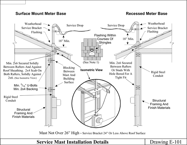
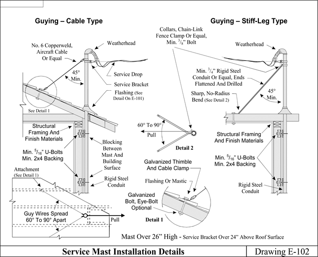
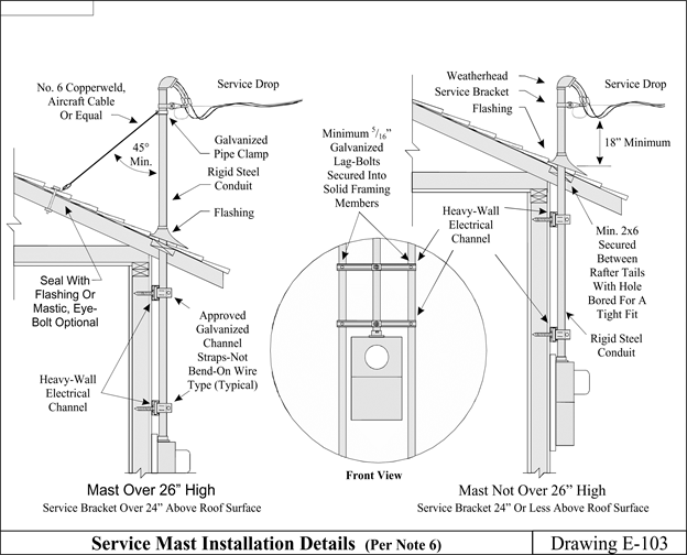
(b) All overhead drops for service, feeder or branch circuits not exceeding #1 AWG aluminum or #3 AWG copper must be rigid steel galvanized conduit no smaller than 1 1/4 inches. The installation must comply with drawings E-101 and/or E-102, or must provide equivalent strength by other approved means. Masts for altered or relocated installations will be permitted to comply with drawing E-103.
 |
 |
 |
Notes to drawings E-101, E-102, and E-103
| (1) | An approved roof flashing must be installed on each mast where it passes through a roof. Plastic, nonhardening mastic must be placed between lead-type flashings and the conduit. Neoprene type flashings will also be permitted to be used. |
| (2) | Masts must be braced, secured, and supported in such a manner that no pressure from the attached conductors will be exerted on a roof flashing, meter base, or other enclosures. |
| (3) | Utilization of couplings for a mast is permitted only below the point the mast is braced, secured, or supported. There must be a minimum of two means of support above any couplings used. A properly installed cable or stiff leg type support qualifies as one of the two required means of support. |
| (4) | Except as otherwise required by the serving utility, service mast support guys must be installed if the service drop attaches to the mast more than 24 inches above the roof line or if the service drop is greater than 100 feet in length from the pole or support. Masts for support of other than service drops must comply with this requirement as well. |
| (5) | Intermediate support masts must be installed in an approved manner with methods identical or equal to those required for service masts. |
| (6) | For altered services, where it is impractical to install U bolt mast supports due to interior walls remaining closed, it will be permissible to use other alternate mast support methods such as heavy gauge, galvanized, electrical channel material that is secured to two or more wooden studs with 5/16 inch diameter or larger galvanized lag bolts. |
| (7) | Conductors must extend at least 18 inches from all mastheads to permit connection to the connecting overhead wiring. |
040 Service conductors - Two-family and multiple-occupancy buildings.
(5) Two-family and multiple-occupancy buildings. A second or additional service drop or lateral to a building having more than one occupancy will be permitted to be installed at a location separate from other service drops or laterals to the building provided that all the following conditions are complied with:
(a) Each service drop or lateral must be sized in accordance with the NEC for the calculated load to be served by the conductors;
(b) Each service drop or lateral must terminate in listed metering/service equipment;
(c) Each occupant must have access to the occupant's service disconnecting means;
(d) No more than six service disconnects may be supplied from a single transformer;
(e) All service drops or laterals supplying a building must originate at the same transformer or power supply;
(f) A permanent identification plate must be placed at each service disconnect location that identifies all other service disconnect locations in or on the building, the area or units served by each, the total number of service disconnecting means on the building/structure and the area or units served. If a structure consists of multiple buildings (i.e., by virtue of fire separation), all service disconnects in or on the entire structure must be labeled to identify all service disconnects in or on the structure; and
(g) A permanent identification plate must be placed at each feeder disconnecting means identifying the area or units served if the feeder disconnecting means is remote from the area or unit served.
042 Service conductor - Size and rating.
(6) For other than one- or two-family dwelling services rated up to 400 amperes, if the service conductors have a lesser ampacity than the overcurrent protection, permitted by NEC 230.90 or NEC 310.15, or the equipment rating that they terminate in or on, an identification plate showing the ampacity of the conductors stating: "Service conductor ampacity: _____" must be installed on the service equipment.
043 Wiring methods for 1,000 volts, nominal or less.
(7) The installation of service conductors not exceeding 1,000 volts, nominal, within a building or structure is limited to the following methods: Galvanized or aluminum rigid metal conduit; galvanized intermediate metal conduit; wireways; busways; auxiliary gutters; minimum schedule 40 rigid polyvinyl chloride conduit; cablebus; or mineral-insulated, metal-sheathed cable (type MI). Exception: Wiring methods per NEC 230.43 shall be permitted for service conductors within a building or structure when those conductors are protected by customer owned supply side overcurrent protection sized per NEC 240.4.
(8) Existing electrical metallic tubing, installed prior to October 1984, which is properly grounded and used for service entrance conductors may be permitted to remain if the conduit is installed in a nonaccessible location and is the proper size for the installed conductors.
(9) In addition to methods allowed in the NEC, the grounded service conductor is permitted to be identified with a yellow jacket or with one or more yellow stripes.
070 Service equipment - Disconnecting means.
(10) The service disconnecting means must be installed at a readily accessible location in accordance with (a) or (b) of this subsection.
(a) Outside location: Service disconnecting means will be permitted on the building or structure or within sight and within 15 feet of the building or structure served. The building disconnecting means may supply only one building/structure. The service disconnecting means must have an identification plate with one-half-inch high letters identifying:
(i) The building/structure served; and
(ii) Its function as the building/structure main service disconnect(s).
(b) Inside location: When the service disconnecting means is installed inside the building or structure, it must be located so that the service raceway extends no more than 15 feet inside the building/structure. Exception: There is no limit to the length of service raceway when conductors are protected by customer owned supply side overcurrent protection sized per NEC 240.4.
085(C) Replacements.
(11) This subsection replaces NEC 230.85(C). When service equipment suppling one- and two-family dwellings is replaced, an emergency disconnecting means must be installed whenever the service ampacity is increased or decreased, or when any of the following are relocated: Service disconnects, meter bases, overhead service masts, or underground service risers.
095 Ground-fault protection of equipment.
(12) Equipment ground-fault protection systems required by the NEC must be tested prior to being placed into service to verify proper installation and operation of the system as determined by the manufacturer's published instructions. This test or a subsequent test must include all service voltage feeders unless the installer can demonstrate, in a manner acceptable to the department, that there are no grounded conductor connections to the feeder(s). A firm having qualified personnel and proper equipment must perform the tests required. A copy of the manufacturer's performance testing instructions and a written performance acceptance test record signed by the person performing the test must be available for the inspector at the time of inspection. The performance acceptance test record must include test details including, but not limited to, all trip settings and measurements taken during the test.